Hotline:+8613549207020


Trending Keywords: Coordinate Measuring Machine
Introduction to Motor Parts: Motor parts refer to components assembled by motor manufacturers to make motors. They mainly consist of stators, rotors, housings, bearings, terminal boxes, fan blades, fan guards and other accessories.
Scope of Application: This is an application case of motor part inspection. The measurement requirements of the part mainly include the flatness of the end face, the concentricity between the central hole and outer circle, as well as the perpendicularity of the central assembly shaft relative to the end face.
Notes on Measurement: A Φ3 mm probe is adopted in this case. The workpiece is placed directly on the marble worktable, so an extended stem is required.
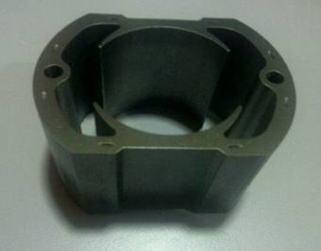
Analysis of Measurement Process: Step 1: Workpiece analysis. According to drawing requirements, flatness, concentricity and perpendicularity of this type of workpiece need to be measured. When measuring perpendicularity, note that the length of the measured cylinder is limited. For measurement accuracy, extension is required during evaluation. The customer does not have a 3D CAD model and only provides physical workpieces. It can be seen from the drawing requirements that the position of the hole and the machining requirement of the surface are critical dimensions during assembly. Establish a suitable coordinate system in accordance with the customer’s drawing requirements, measure and obtain required features, and compile a complete program to facilitate subsequent batch inspection. The physical workpiece is shown as follows:
Step 2: Workpiece clamping. After understanding the datums and measurement requirements, workpiece clamping can be carried out. This workpiece is a metal part, so it can be fixed on the marble work surface simply by clamping with a bench vice.
5. Specific Measurement Procedures:
Probe calibration: All measurement features in this case lie on one plane, so only one angle A0B0 is required.
Manual coordinate system establishment: For this workpiece, the coordinate system is defined by plane-circle-circle, with the origin set at the center. Simple features can be selected for manual coordinate system setup.
Automatic coordinate system establishment: The coordinate system is established in the same way as the manual method. More points are sampled on the measured surface for subsequent flatness evaluation.
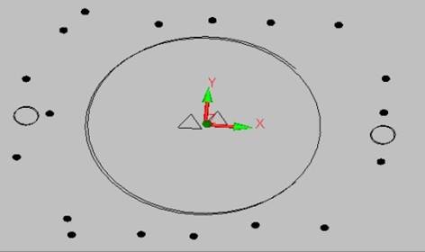
Measurement features: Measure the characteristic features required for evaluating perpendicularity and concentricity.
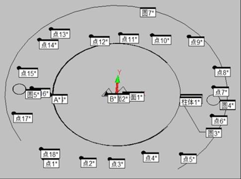
5.Evaluation:
Flatness: Evaluate by using the plane constructed from measured points.
Concentricity: Take the inner hole circle as the datum to evaluate the concentricity of the outer circle relative to it.
Perpendicularity: Define the plane as the datum to evaluate the perpendicularity of the cylinder to this plane. Extend the cylinder length during evaluation.
6、Output the report.
6.Recommended Machine Model and Probe Configuration for Motor Parts Inspection Case:
Model: Croma
Probe Configuration: TESASTAR-M7.5-M8 + TESASTAR-P
 +8613549207020(Ms. Li)
Tel:0769-85727276
Email:wh@dgwhjm.com
Address:Building M, Meishida Industrial Park, Nansha 6th Industrial Zone, Humen Town, Dongguan City, Guangdong Province, P.R.China (Headquarters)